Pulse width modulator
•Generates pulses with specific
high/low times
•Duty cycle: % time high
–Square wave: 50% duty cycle
•Common use: control average voltage
to electric device
–Simpler than DC-DC converter or
digital-analog converter
–DC motor speed, dimmer lights
•Another use: encode commands,
receiver uses timer to decode
1
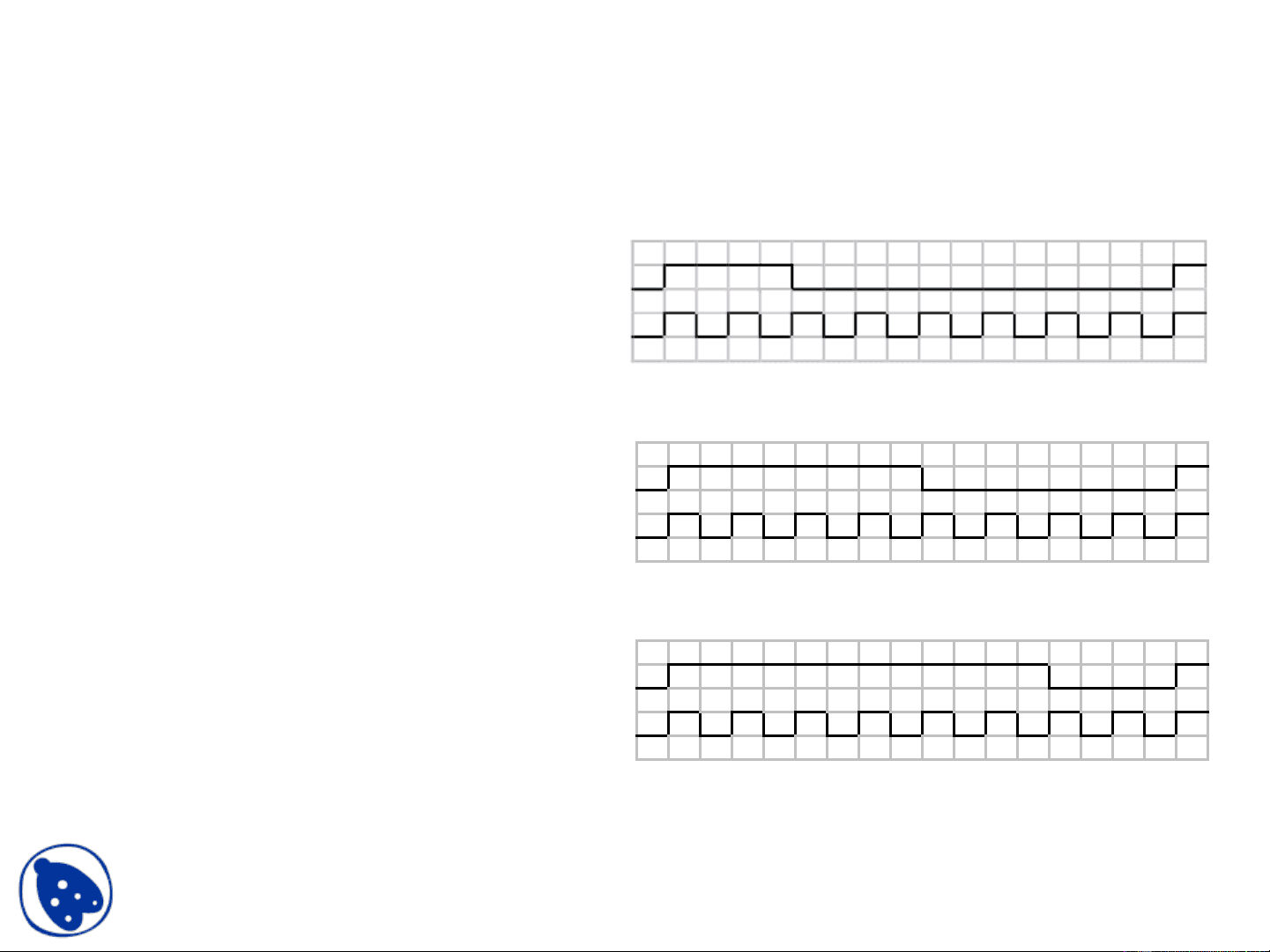
clk
pwm_o
25% duty cycle – average pwm_o is 1.25V
clk
pwm_o
50% duty cycle – average pwm_o is 2.5V.
clk
pwm_o
75% duty cycle – average pwm_o is 3.75V.
Docsity.com