Download Prestressed Concrete: Advantages, Disadvantages, and Analysis and more Study Guides, Projects, Research Civil Engineering in PDF only on Docsity!
Lecture 24 – Prestressed Concrete
Prestressed concrete refers to concrete that has applied stresses induced into the member. Typically, wires or “tendons” are stretched and then blocked at the ends creating compressive stresses throughout the member’s entire cross- section. Most Prestressed concrete is precast in a plant.
Advantages of Prestressed concrete vs. non-Prestressed concrete:
- More efficient members (i.e., smaller members to carry same loads)
- Much less cracking since member is almost entirely in compression
- Precast members have very good quality control
- Precast members offer rapid field erection
Disadvantages of Prestressed concrete vs. non-Prestressed concrete:
- More expensive in materials, fabrication, delivery
- Heavy precast members require large cranes
- Somewhat limited design flexibility
- Small margin for error
- More complicated design
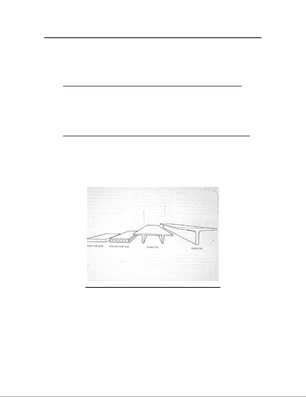
Typical Precast Prestressed concrete members
Pre-Tensioned Prestressed Concrete:
Pre-tensioned concrete is almost always done in a precast plant. A pre- tensioned Prestressed concrete member is cast in a preformed casting bed. The BONDED wires (tendons) are tensioned prior to the concrete hardening. After the concrete hardens to approximately 75% of the specified compressive strength f’c, the tendons are released and axial compressive load is then transmitted to the cross-section of the member.
“Dead” end “Live” end
Tendons tensioned between bulkheads Prestress force Ps Casting bed
Tendons anchored at “Live” end and “Dead” end
Fresh concrete placed in bed
Tendons released at “Live” end and “Dead” end creating an axial force along length of precast member
Prestress force Ps
Hardened concrete
Step 1
Step 2
Step 3
a = f b
A f
c
ps ps
- 85 '
dp h
b
N.A.
yt
yb e
Aps
Rectangular Prestressed Beam
Example
GIVEN: The rectangular prestressed concrete beam as shown below. Use the following:
- Concrete f’c = 5000 PSI
- Concrete strength = 75%(f’c ) at time of prestressing
- Aps = 3 – ½” dia. 7-wire strands @ 0.153 in 2 per strand = 0.459 in^2
- f (^) pu = 270 KSI (using an ordinary 7-wire strand)
- Initial prestress force, P (^) s = 70%(fpu )(Aps )
- Service dead load, (NOT including beam weight) = 400 PLF
- Service beam weight = 188 PLF
- Service live load = 1500 PLF
REQUIRED:
- Determine the location of the neutral axis and prestress eccentricity “e”.
- Determine the moment of inertia about the neutral axis, Ig.
- Determine the stresses during prestressing.
- Determine the stresses during initial applied service beam weight.
- Determine the stresses due to service applied dead load + live load.
- Determine the final stresses due to all service loads and prestressing.
- Determine the maximum actual factored moment on the beam Mmax.
- Determine the factored usable moment capacity M (^) u of the beam.
N.A.
yt
yb e
Rectangular Prestressed Beam Aps = 0.459 in 2
Step 2 – Determine the moment of inertia about the neutral axis, Ig:
Ig = 2
3 2 ( ) 12 2
nA e h bh y bh t ⎟ + ps ⎠
+ ⎛^ −
3 2 ( 3. 30 )( 6. 87 ") 2
⎟ + in ⎠
= 4860 in^4 + 3.0 in^4 + 155.7 in^4
Ig = 5018.7 in^4
Step 3 – Determine the stresses during prestressing:
f = g
s g
s I
Pey A
P
where: Ps = prestress force = 70%(f (^) pu )(Aps ) = 0.70(270 KSI)(0.459 in 2 ) = 86.8 KIPS
y = yt for tensile stresses at top of beam = y (^) b for compressive stresses at bottom of beam
a) Check stresses at TOP of beam:
f (^) top = stress at top of beam
g
s t g
s I
Pey A
P
in
KIPS
x
KIPS
= -0.48 KSI + 1.08 KSI
f (^) top = 0.60 KSI Tension
b) Check stresses at BOTTOM of beam:
f (^) bottom = stress at bottom of beam
g
s b g
s I
Pey A
P
in
KIPS
x
KIPS
= -0.48 KSI - 1.05 KSI
f (^) bottom = -1.53 KSI Compression
Step 4 – Determine the stresses during initial applied service beam weight:
f = g
beam I
M ( y ) ±
where: M (^) beam = maximum unfactored moment due to beam wt.
wbeam ( L )^2
( 188 PLF )( 22 ' − 0 ")^2
= 11,374 Lb-Ft = 11.4 KIP-FT
y = yt for compression in^ top = yb for tension in bottom
a) Check stresses at TOP:
f (^) top = g
beam t I
M ( y ) −
in
KIP − FT ft −
f (^) top = -0.25 KSI Compression
b) Check stresses at BOTTOM:
f (^) bottom = g
DLLL b I
M (^) + ( y )
in
KIP − FT ft
f (^) bottom = 2.44 KSI Tension
Step 6 – Determine the final stresses due to all service loads and prestressing:
Step 7 – Determine the maximum actual factored moment on the beam M (^) max:
M (^) max = 8
w L^2 u
wu = 1.2D + 1.6L = 1.2(400 PLF + 188 PLF) + 1.6(1500 PLF) = 3106 PLF = 3.1 KLF
M (^) max = 8
3. 1 ( 22 ' − 0 )^2
M (^) max = 188 KIP-FT
Initial Prestress
= +^ =
-0.48C +1.08T -0.25C^ +0.35T -2.51C^ -2.16C
-0.48C -1.05C +0.24T -1.29C +2.44T +1.15T
g
s A
− P
g
s I
Beam Wt. Transfer DL + LL Final
NOTE: All stresses shown have units of KSI
ACI dictates the following maximum permissible stresses at service loads:
a) Compression = 0.60f’ (^) c b) Tension = 6 f ' c
Step 8 – Determine the factored usable moment capacity Mu of the beam:
M (^) u = 0.9Aps f (^) ps (dp - 2
a )
where:
fps = (^) ⎟⎟ ⎠
c
pu p
p pu (^) f
f f '
1
f (^) pu = ultimate tensile strength of prestressing tendon = 270 KSI
γp = factor based on the type of prestressing steel = 0.40 for ordinary wire strand
β1 = 0.80 for concrete f’c = 5000 PSI
ρp = p
ps bd
A
- 453 in^2
f (^) ps = (^) ⎟⎟ ⎠
KSI
KSI
KSI
= 249.4 KSI
a = f b
A f
c
ps ps
- 85 '
KSI
in KSI
M (^) u = 0.9Aps f (^) ps (dp - 2
a )
= 0.9(0.453 in^2 )(249.4 KSI)(16” - 2
= 1492 Kip-In
M (^) u = 124.3 KIP-FT < M (^) max = 188 KIP-FT → NOT ACCEPTABLE