Download 3D Transformations, Windowing, and Clipping in Computer Graphics and more Essays (university) Computer Graphics in PDF only on Docsity!
BCA VI Semester
BCA 601:Computer Graphics and Multimedia
Unit III
3D Transformation :
In 3D graphics, transformation is often used to operate on vertices and vectors. It is also used to convert
them in one space to another. Transformation is performed via multiplication with a matrix. There are
typically three types of primitive transformation that can be performed on vertices: translation (where it
lies in space relative to the origin), rotation (its direction in relation to the x, y, z frame), and scaling (its
distance from origin). In addition to those, projection transformation is used to go from view space to
projection space.
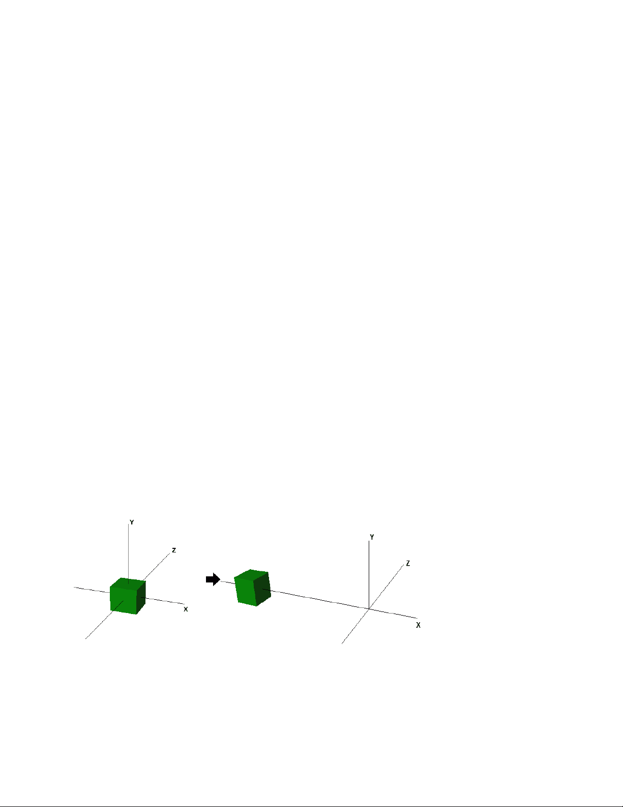
Translation:
Translation refers to moving or displacing for a certain distance in space. Similar to 2D transformations, which used 3x3 matrices, 3D transformations use 4X4 matrices (X, Y, Z, W).If point (X,Y,Z) is to be translated by amount tx, ty and tz to location (X',Y',Z')
X' = tx + X Y' = ty + Y Z' = tz + Z
or P' = T * P where
P' = X' T = 1 0 0 tx P= X
Y' 0 1 0 ty = T(tx,ty,tz) Y Z' 0 0 1 tz Z 1 0 0 0 1 1 1
The effect of translation:
In 3D, a space is typically defined by an origin and three unique axes from the origin: X, Y and Z. There
are several spaces commonly used in computer graphics: object space, world space, view space,
projection space, and screen space.
Rotation: Rotation refers to rotating vertices about an axis going through the origin. Three such axes are
the X, Y, and Z axes in the space. For 3D rotation we need to pick an axis to rotate about. The most
common choices are the X-axis, the Y-axis, and the Z-axis
Here are the matrices for rotation by α around the x -axis, β around the y -axis, and γ around
the z -axis.
Following figure explains the rotation about various axes −
Scaling: In 3D scaling operation, three coordinates are used. Let us assume that the original
coordinates are (X, Y, Z), scaling factors are ( S X , S Y , Sz ) respectively, and the produced coordinates are
(X’, Y’, Z’). This can be mathematically represented as shown below –
Sx 0 0 0 S= 0 Sy0 0 P’=P.S X’ Y’ Z’ 1 = X Y Z 1 Sx^0 0 0 0 0 1 0 0 Sy 0 0 0 0 0 10 0 1 0 0 0 0 1
= X.SxY.SyZ.Sz 1
Indore Indira School Of Career Studies
Line Clipping
The concept of line clipping is same as point clipping. In line clipping, we will cut the portion of line which is outside of window and keep only the portion that is inside the window.
Cohen-Sutherland Line Clippings
This algorithm uses the clipping window as shown in the following figure. The minimum coordinate for the clipping region is (XWmin,YWmin)(XWmin,YWmin) and the maximum coordinate for the clipping region is (XWmax,YWmax)(XWmax,YWmax).
We will use 4-bits to divide the entire region. These 4 bits represent the Top, Bottom, Right, and Left of the region as shown in the following figure. Here, the TOP and LEFT bit is set to 1 because it is the TOP-LEFT corner.
There are 3 possibilities for the line −
Indore Indira School Of Career Studies
- Line can be completely inside the window (This line will be completely removed from the region).
- Line can be completely outside of the window (This line will be completely removed from the region).
- Line can be partially inside the window (We will find intersection point and draw only that portion of line that is inside region).
Algorithm
Step 1 − Assign a region code for each endpoints. Step 2 − If both endpoints have a region code 0000 then accept this line. Step 3 − Else, perform the logical AND operation for both region codes. Step 3.1 − If the result is not 0000, then reject the line. Step 3.2 − Else you need clipping. Step 3.2.1 − Choose an endpoint of the line that is outside the window. Step 3.2.2 − Find the intersection point at the window boundary (base on region code). Step 3.2.3 − Replace endpoint with the intersection point and update the region code. Step 3.2.4 − Repeat step 2 until we find a clipped line either trivially accepted or trivially rejected. Step 4 − Repeat step 1 for other lines.
Polygon Clipping (Sutherland Hodgeman Algorithm)
A polygon can also be clipped by specifying the clipping window. Sutherland Hodgeman polygon clipping algorithm is used for polygon clipping. In this algorithm, all the vertices of the polygon are clipped against each edge of the clipping window.
First the polygon is clipped against the left edge of the polygon window to get new vertices of the polygon. These new vertices are used to clip the polygon against right edge, top edge, bottom edge, of the clipping window as shown in the following figure.
While processing an edge of a polygon with clipping window, an intersection point is found if edge is not completely inside clipping window and the a partial edge from the intersection point to the outside edge is clipped. The following figures show left, right, top and bottom edge clippings −
In all or none string clipping method, either we keep the entire string or we reject entire string based on the clipping window. As shown in the above figure, STRING2 is entirely inside the clipping window so we keep it and STRING1 being only partially inside the window, we reject.
The following figure shows all or none character clipping −
This clipping method is based on characters rather than entire string. In this method if the string is entirely inside the clipping window, then we keep it. If it is partially outside the window, then −
- You reject only the portion of the string being outside
- If the character is on the boundary of the clipping window, then we discard that entire character and keep the rest string. The following figure shows text clipping −
This clipping method is based on characters rather than the entire string. In this method if the string is entirely inside the clipping window, then we keep it. If it is partially outside the window, then
- You reject only the portion of string being outside.
- If the character is on the boundary of the clipping window, then we discard only that portion of character that is outside of the clipping window.
Bitmap Graphics
A bitmap is a collection of pixels that describes an image. It is a type of computer graphics that the computer uses to store and display pictures. In this type of graphics, images are stored bit by bit and hence it is named Bit-map graphics. For better understanding let us consider the following example where we draw a smiley face using bit-map graphics.
Now we will see how this smiley face is stored bit by bit in computer graphics.
By observing the original smiley face closely, we can see that there are two blue lines which are represented as B1, B2 and E1, E2 in the above figure. In the same way, the smiley is represented using the combination bits of A4, B5, C6, D6, E5, and F respectively. The main disadvantages of bitmap graphics are −
- We cannot resize the bitmap image. If you try to resize, the pixels get blurred.
- Colored bitmaps can be very large.
Window to view port transformation:
• World Coordinate System - This is object space or the space in which the application model
is defined.
• Screen Coordinate System - The space in which the image is displayed.
Indore Indira School Of Career Studies
Using this proportionality, the following ratios must be equal.
By solving these equations for the unknown viewport position (xv, yv), the following becomes true:
The scale factors (Sx, Sy) would be:
And the translation factors (Tx, Ty) would be:
Indore Indira School Of Career Studies
The position of the viewport can be changed allowing objects to be viewed at different positions on the Interface Window. Multiple viewports can also be used to display different sections of a scene at different screen positions. Also, by changing the dimensions of the viewport, the size and proportions of the objects being displayed can be manipulated. Thus, a zooming affect can be achieved by successively mapping different dimensioned clipping windows on a fixed sized viewport.If the aspect ratio of the world window and the viewport are different, then the image may look distorted.
Zooming or Panning Using Window-to-Viewport transformation
Zooming is a technique in which users can change the size of the area to be viewed in order to see more detail or less detail. Panning or roaming means sliding the camera across the scene, taking in different parts of it at different times. Both zooming and panning can be achieved in computer graphics by leaving the viewport static and changing the world window. The picture below (taken from wikipedia.org) shows these concepts.
Display file: A display file is a set of uncorrelated data, such as a histogram array or bivariate array. The
arrays are filled event by event from a list data in order to create a display. The saved arrays usually take up for less disk space, but can the data can no longer be gated.A display file consists of a set of commands to make an image. A display file interpreter is used to translate these commands and to make
file starting location for that segment, the second array holds segment size information, while the third indicates the visibility and so on.
Figure SEQ Figure * ARABIC 1:Segment Table and Display file
Figure SEQ Figure * ARABIC 2: Segment Table
Function of a segment table:
- Create segment
- Close segment
- Delete segment
- Rename segment Algorithm for segment creation: 1.Check whether any segment is open;if so display error message:”Segment is still open ” and go to step 9 2.Read the name of new segment. 3.Check whether the new segment name is valid;if not display error message:”Not a valid segment name” and go to step 9. 4.Check whether segment name already exists in the same- name list; If so display error message:” Segment name already exists” and go to step 9.
- Initialize the start of the segment at the next free storage area in the display file.
- Initialize size of this segment equal to zero.
- Initialize all attributes of segment to their default values.
- Indicate that the new segment is now open.
- Stop.
Algorithm for segment closing:
- Check whether any segment is open; if no display error message: ”No segment open ” and go to step 6.
- Change the name of currently open segment, say 0,i.e. unnamed segment.
- Delete any unnamed segment instructions which may have been saved,i.e. initialize the unnamed segment with no instructions.
- Initialize the start of the unnamed segment at the next free storage area in the display file.
- Initialize size of unnamed segment equal to 0.
- Stop.
Algorithm for segment deleting:
- Read the name of segment which is to be deleted. 2.Check whether that segment name is valid; if not, display error message: ”Segment not valid” and go to step 8 3.Check whether the segment is open; if yes, display error message: ”Can’t delete the open segment ” and go to step 8 4.Check whether the size of segment is greater than 0;if no,no processing is required,as segment contains no instructions.Therefore, go to step 5.Shift the display file elements which follow the segment which is to be deleted by its size.
- Recover the deleted space by resetting the index of the next free instruction.
- Adjust the starting positions of the shifted segments by subtracting the size of the deleted segment from it.
- Stop Algorithm for segment renaming: 1.Check whether both old and new segment names are valid; if not, display error message: ” Not valid segment names” and go to step 6 2.Check whether any of the two segments are open; if open, display error message: ”Segments still open” and go to step 6 3.Check whether the new name we are going to give to the old segment is not already existing in the display file. If yes, display error message” Segment already exists” and go to step 6 4.Copy the old segment table entry into the new position. 5.Delete the old segment.
- Stop
Indore Indira School Of Career Studies