Download INDUSTRIAL CASTING TECHNOLOGY and more Study Guides, Projects, Research Manufacturing Technologies in PDF only on Docsity!
UNIT-I
PATTERNS AND MOULDING SANDS
INTRODUCTION TO CASTING
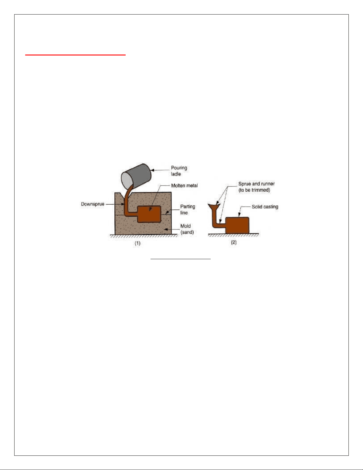
Casting is a process in which molten metal flows by gravity or other force into a mould where it solidifies in the shape of the mould cavity. The term casting is also applied to the part that is made by this process. The principle of casting seems simple: melt the metal pour it into a mould and let it cool and solidify Yet there are many factors and variables that must be considered in order to accomplish a successful casting operation.
Fig 1.1 Casting Process
Advantages of Casting Casting can be used to create complex part geometries, including both external and internal shapes. Some casting processes are capable of producing parts to net shape. No further manufacturing operations are required to achieve the required geometry and dimensions of the parts. Casting can be used to produce very large parts. Castings weighing more than 100 tons have been made. The casting process can be performed on any metal that can be heated to the liquid state. Some casting methods are quite suited to mass production. Disadvantages of casting Limitations on mechanical properties, porosity Poor dimensional accuracy and surface finish for some casting processes. Safety hazards to humans when processing hot molten metals, and environmental problems
STEPS IN CASTING
Pattern and Mould Melting and Pouring Solidification and Cooling Removal, Cleaning, Finishing and Inspection
PATTERN
The pattern is the principal tool during the casting process. It is the replica of the object to be made by the casting process, with some modifications. The main modifications are the addition of pattern allowances, and the provision of core prints. If the casting is to be hollow, additional patterns called cores are used to create these cavities in the finished product. The quality of the casting produced depends upon the material of the pattern, its design, and construction. The costs of the pattern and the related equipment are reflected in the cost of the casting. The use of an expensive pattern is justified when the quantity of castings required is substantial.
Fig 1.2 a typical pattern attached with gating and risering system
Functions of the Pattern
- A pattern prepares a mould cavity for the purpose of making a casting.
- A pattern may contain projections known as core prints if the casting requires a core and need to be made hollow.
- Runner, gates, and risers used for feeding molten metal in the mould cavity may form a part of the pattern.
- Patterns properly made and having finished and smooth surfaces reduce casting defects.
- A properly constructed pattern minimizes the overall cost of the castings.
PATTERN MATERIAL
Patterns may be constructed from the following materials. Each material has its own advantages,
- Easily worked, shaped and joined
- Light in weight
- Strong, hard and durable
- Resistant to wear and abrasion
- Resistant to corrosion, and to chemical reactions
- Dimensionally stable and unaffected by variations in temperature and humidity
- Available at low cost The usual pattern materials are wood, metal, and plastics. The most commonly used pattern material is wood, since it is readily available and of low weight. Also, it can be easily shaped and is relatively cheap. The main disadvantage of wood is its absorption of moisture, which can cause distortion and dimensional changes. Hence, proper seasoning and upkeep of wood is almost a pre-requisite for large-scale use of wood as a pattern material. COMMON PATTERN MATERIALS The common materials used for making patterns are wood, metal, plastic, plaster, wax or mercury. The some important pattern materials are discussed as under. 1. WOOD Wood is the most popular and commonly used material for pattern making. It is cheap, easily available in abundance, repairable and easily fabricated in various forms using resin and glues. It is very light and can produce highly smooth surface. Wood can preserve its surface by application of a shellac coating for longer life of the pattern. But, in spite of its above qualities, it is susceptible to shrinkage and warpage and its life is short because of the reasons that it is highly affected by moisture of the moulding sand. After some use it warps and wears out quickly as it is having less resistance to sand abrasion. It cannot withstand rough handily and is weak in comparison to metal. In the light of above qualities, wooden patterns are preferred only when the numbers of castings to be produced are less. The main varieties of woods used in pattern-making are shisham, kail, deodar, teak and mahogany. a) Shisham It is dark brown in color having golden and dark brown stripes. It is very hard to work and blunts the cutting tool very soon during cutting. It is very strong and durable. Besides making pattern, it is also used for making good variety of furniture, tool handles, beds, cabinets, bridge piles, plywood etc. b) Kail It has too many knots. It is available in Himalayas and yields a close grained, moderately hard and durable wood. It can be very well painted. Besides making pattern, it is also utilized for making wooden doors, packing case, cheap furniture etc.
c) Deodar It is white in color when soft but when hard, its color turns toward light yellow. It is strong and durable. It gives fragrance when smelled. It has some quantity of oil and therefore it is not easily attacked by insects. It is available in Himalayas at a height from 1500 to 3000 meters. It is used for making pattern, manufacturing of doors, furniture, patterns, railway sleepers etc. It is a soft wood having a close grain structure unlikely to warp. It is easily workable and its cost is also low. It is preferred for making pattern for production of small size castings in small quantities. d) Teak Wood It is hard, very costly and available in golden yellow or dark brown color. Special stripes on it add to its beauty. In India, it is found in M.P. It is very strong and durable and has wide applications. It can maintain good polish. Besides making pattern, it is used for making good quality furniture, plywood, ships etc. It is a straight-grained light wood. It is easily workable and has little tendency to warp. Its cost is moderate. e) Mahogany This is a hard and strong wood. Patterns made of this wood are more durable than those of above mentioned woods and they are less likely to warp. It has got a uniform straight grain structure and it can be easily fabricated in various shapes. It is costlier than teak and pine wood, It is generally not preferred for high accuracy for making complicated pattern. It is also preferred for production of small size castings in small quantities. The other Indian woods which may also be used for pattern making are deodar, walnut, kail, maple, birch, cherry and shisham. Advantages of wooden patterns
- Wood can be easily worked.
- It is light in weight.
- It is easily available.
- It is very cheap. Disadvantages
- It is susceptible to moisture.
- It tends to warp.
- It is easy to join.
- It is easy to obtain good surface finish.
- Wooden laminated patterns are strong.
- It can be easily repaired.
- It wears out quickly due to sand abrasion.
- It is weaker than metallic patterns. 2. METAL Metallic patterns are preferred when the number of castings required is large enough to justify their use. These patterns are not much affected by moisture as wooden pattern. The wear and tear of this pattern is very less and hence possess longer life. Moreover, metal is easier to shape the pattern with good precision,
The main disadvantages of metallic patterns are higher cost, higher weight and tendency of rusting.It is preferred for production of castings in large quantities with same pattern. The metals commonly used for pattern making are cast iron, brass and bronzes and aluminum alloys. a) Cast Iron It is cheaper, stronger, tough, and durable and can produce a smooth surface finish. It also possesses good resistance to sand abrasion. The drawbacks of cast iron patterns are that they are hard, heavy, and brittle and get rusted easily in presence of moisture. Advantages
- It is cheap
- It is easy to file and fit
- It is strong Disadvantages
- It is heavy
- It is brittle and hence it can be easily broken
- It may rust b) Brasses and Bronzes
- It has good resistance against sand abrasion
- Good surface finish
These are heavier and expensive than cast iron and hence are preferred for manufacturing small castings. They possess good strength, machinability and resistance to corrosion and wear. They can produce a better surface finish. Brass and bronze pattern is finding application in making match plate pattern Advantages
- Better surface finish than cast iron.
- Very thin sections can be easily casted. c) Aluminum Alloys
Disadvantages
- It is costly
- It is heavier than cast iron. Aluminum alloy patterns are more popular and best among all the metallic patterns because of their high light ness, good surface finish, low melting point and good strength. They also possesses good resistance to corrosion and abrasion by sand and thereby enhancing longer life of pattern. These materials do not withstand against rough handling. These have poor repair ability and are preferred for making large castings.
Advantages
- Aluminum alloys pattern does not rust.
- They are easy to cast.
- They are light in weight.
- They can be easily machined.
Disadvantages
- They can be damaged by sharp edges.
- They are softer than brass and cast iron.
- Their storing and transportation needs proper care.
d) White Metal (Alloy of Antimony, Copper and Lead) Advantages
- It is best material for lining and stripping plates.
- It has low melting point around 260°C
- It can be cast into narrow cavities. 3. PLASTIC
Disadvantages
- It is too soft.
- Its storing and transportation needs proper care
- It wears away by sand or sharp edges. Plastics are getting more popularity now a days because the patterns made of these materials are lighter, stronger, moisture and wear resistant, non-sticky to moulding sand, durable and they are not affected by the moisture of the moulding sand. Moreover they impart very smooth surface finish on the pattern surface. These materials are somewhat fragile, less resistant to sudden loading and their section may need metal reinforcement. The plastics used for this purpose are thermosetting resins. Phenolic resin plastics are commonly used. These are originally in liquid form and get solidified when heated to a specified temperature. To prepare a plastic pattern, a mould in two halves is prepared in plaster of Paris with the help of a wooden pattern known as a master pattern. The phenolic resin is poured into the mould and the mould is subjected to heat. The resin solidifies giving the plastic pattern. Recently a new material has stepped into the field of plastic which is known as foam plastic. Foam plastic is now being produced in several forms and the most common is the expandable polystyrene plastic category. It is made from benzene and ethyl benzene. 4. PLASTER This material belongs to gypsum family which can be easily cast and worked with wooden tools and preferable for producing highly intricate casting. The main advantages of plaster are that it has high compressive strength and is of high expansion setting type which compensate for the shrinkage allowance of the casting metal. Plaster of Paris pattern can be prepared either by directly pouring the slurry of plaster and water in moulds prepared earlier from a master pattern or by sweeping it into desired shape or form by the sweep and strickle method. It is also preferred for production of small size intricate castings and making core boxes. 5. WAX Patterns made from wax are excellent for investment casting process. The materials used are blends of several types of waxes, and other additives which act as polymerizing agents, stabilizers, etc. The commonly used waxes are paraffin wax, shellac wax, bees-wax, cerasin wax, and micro-crystalline wax. The properties desired in a good wax pattern include low ash content up to 0.05 per cent, resistant to the primary coat material used for investment, high tensile strength and hardness, and substantial weld strength.
(1) Woodworking Lathe The woodworking lathe is one of the most important machines to the patternmaker since patterns and core boxes often involve some sort of cylindrical work. It is designed chiefly for turning jobs, both external and internal. However, by suitably manipulating the tool, tapers, and radii, other irregular shapes can also be easily turned. The woodworking lathe (Fig 1.3) consists of four major parts are the head stock, which has a spur or live centre fitted in a hollow spindle; the tail stock, carrying a dead centre; a tool rest, which is stationary and adjustable; and a bed to which are fastened the other three parts.
Fig 1.3 Woodworking lathe Pattern shops are equipped with a special type of woodworking lathe, known as the patternmaker’s lathe. This lathe is a modified version of the woodworking lathe and in many respects resembles the centre lathe used for metal-working operations. The design of its various parts makes it more robust and sturdy and therefore more dependable than the woodworking lathe. First, the patternmaker's lathe has a back gearing arrangement by means of which the available number of spindle speeds is doubled. Secondly, it is equipped with a feed shaft and a sliding carriage in place of the fixed-type tool rest. On the carriage is fitted a cross slide, a compound slide, and a tool post. Thus, in this lathe, the tool traverse, both parallel to the work axis as well as across it, can be precisely regulated for better size control. The size of woodworking lathes is usually specified in terms of the swing or height-of-centre of the lathe and the maximum distance between the centres. The height-of-centre is taken as the distance from the lathe centre to the upper surface of the bed, and the swing is double that of the height-of-centre. Generally, the woodworking lathe is supplied together with a number of accessories, which considerably increase its usefulness and adaptability. Some of the typical accessories include different types of centres, such as drive centre, cup centre, and screw centre, a face plate, a 4-jaw independent chuck, a 3-jaw self-centring chuck, a tool holder, and a set of wood turning tools. The types of tools commonly
used on these lathes are illustrated in Fig 1.4. The material of these tools is high carbon steel containing about 0.8-1.0% carbon.
Fig 1.4 woodworking lathe tools (2) Circular Saw The circular saw is also an essential machine in the pattern shop. It can be used for all cutting operations, such as ripping, cross-cutting, beveling, rabbeting, grooving, and mitering. The principal parts of the circular saw are a cast-iron table upon which the work is supported and from where it is fed into the saw. A circular saw blade supported in bearing on the underside of the table and rotating at high speed, a driving arrangement for the saw blade, consisting of an electric motor and a set of pulleys mounted on shafts. A cut-off guide, which is used during cross-cutting to steer the piece towards the saw blade and a ripping fence, which acts as a guide while sawing along the grains of wood. The circular saw usually has provision for tilting the table, thus enabling cutting at an angle as required during mitering, beveling, etc. The tilting can be done up to an angle of 45°. The size of the circular saw is specified by the diameter of the saw blade. A 300-mm saw is commonly used for small and medium-sized work. The cutting speeds for sawing vary from 1000 metres to 3000 metres per minute according to the hardness of the wood. (3) Band Saw The band saw makes use of an endless metal saw band, which travels over the rim of two rotating pulleys. Although the number of operations that can be performed on a band saw is less than those on a circular saw, it is favoured for curved or irregular cuts in wood. The main parts of a band saw are the following: (i) A set of cast-iron pulleys or wheels carrying the saw band on their periphery; of the two wheels, one is adjustable and the other is fixed so that the centre-to-centre distance can be slightly varied to maintain proper tension of the band
Fig 1.5 Wood Jointer
(6) Planer The purpose of a wood planer is similar to that of a jointer, but it is designed primarily for planing large and heavy stock at a comparatively faster rate and involving a lesser amount of manual labour (Fig. 2.8). The boards to be planed are fed into the machine by means of feed rolls along a table against a revolving cutter head, thus eliminating the labour of hand feeding. The cutter head is mounted on an overhead shaft which is adjustable for regulating the depth of the cut (Fig 1.6). The table of the planer is generally much wider and longer than that of a jointer and more accommodating for large plants. The planer is also usually equipped to automatically surface the wood to desired thicknesses.
Fig 1.6 Principle parts of a wood Planer Fig 1.7 Cross section of cutter
(7) Shaper The machine consists of a cutter head, carrying a cutter and rotating about a vertical axis, and a horizontal table similar to that of a jointer. The wood is fed by hand along the table against the cutter and guided by an adjustable fence, Fig. 1.8(A). The shape of the cut on the surface of the wood is the same as that of the profile of the teeth on the cutter. By suitably designing the cutter, a variety of shapes can be produced. The types of cut that can be taken by a shaper are shown in Fig. 1.8(B).
Fig. 1.8 (A) Wood shaper; Fig. 1.8 (B) Types of cut taken by a wood shaper
(8) Pattern Milling Machine This machine has a large base on which a broad column is supported as shown in Fig 1.9. At the front of the base is a table support, which slides on rails and can be locked in the desired position. The workpiece is mounted on the table and it can be moved along both X-X and Y-Y axes, all the three movements being usually hand-operated. The column carries an overhanging arm which can be raised or lowered, both manually and by power operation. At the outer end of the arm is the spindle head, and cutter spindle. The spindle can be raised, lowered, and canted on both sides through 45° on the right and 30° on the left, working in vertical, horizontal, and any angular position. Six spindle speeds are provided varying from 850 to 4200 rpm. The machine is equipped with several tools and cutters, such as a pattern cutter, core box cutter, fillet cutter, and boring cutter, and gauging and recessing tools. The pattern-milling machine, by virtue of its expansive table movements, the long vertical movement of its arm, the flexibility of its spindle, and its wide range of tools, cutters and accessories, is capable of numerous operations. These operations include boring, drilling, milling, facing, slotting, grooving, shaping, fillet cutting, gear-cutting, worm-cutting and forming the radius, angular cuts and other shapes as required in the core box.The speeds and feeds needed for woodworking machines are as shown in Table 2.2. The workability of wood on the machines depends on its specific gravity, moisture content, and the directional arrangement of grains. For instance, low moisture content (about 6%) offers excellent conditions for machining. The type of operation has considerable influence on the quality of work. Surface cutting speeds, also regulated by the foregoing factors, range from 1200 metres per minute to 3000 metres per
of the disc. An adjustable table is provided against the disc on which the job to be sanded is placed and pressed. A bobbin sander consists of a cylindrical bobbin of 75-mm diameter and 200-mm length around which again sandpaper can be attached. The bobbin, while it rotates at high speed, also moves up and down through a short stroke of about 50 mm. A work support or table is provided around the bobbin. Curved surfaces, which cannot be sanded on the disc sander, can be finished on the bobbin sander. Disc and bobbin mechanisms are often combined in a single unit called the disc-cum-bobbin sander in which one electric motor drives both the disc and the bobbin. Special sandpapers in different grades of fine nesses are available for the machine. Dust Exhaust System Woodworking machines, such as saws and sanders produce very fine dust which, if left uncollected, stays suspended in the atmosphere. Sawdust from the sander is also hot and can be dangerous. Dust exhaust systems should be installed on all such machines so that the dust is collected and disposed of in a convenient manner. A proper dust-collection system helps in maintaining a clean working environment and thus improves efficiency, besides preventing fire hazards and protecting the health of the workers. There should be an exhaust system, either one for each machine or a central exhaust system, which collects dust from various machines by means of a common suction fan. The exhaust system consists of a hood or some other suitable arrangement to collect the dust and shavings, suction fan, a filtering arrangement for exuding clean air, a chamber for the collection of dust, and suitable pipelines. The filtering arrangement is usually of the 'bag-filter' type, which allows only clean air to pass through a series of bags and then escape to the atmosphere, thus separating it from dust. There is also a vibratory system which periodically shakes the bags to rid them of the dust particles sticking to their linings. Modern woodworking machines are equipped with a built-in dust exhaust system, which is cleaner and more compact than the system installed as an appendage. (10) Machines for Tool Grinding In order to efficiently use the woodworking machines, their tools and cutters have to be periodically sharpened and kept trim. It is not possible to grind or sharpen all the diverse types of tools by hand grinding. Equipment that is essential includes a circular saw and band saw blade sharpener (either in two separate machines or in the same machine); a band saw blade butt welder; a planer knife grinder; a tool and cutter grinder; and a double- ended tool grinder. Hand Tools for Wood Patternmaking Wood patternmaking is basically a woodworking process since a majority of the patterns used in the foundry are made in wood. Most of the tools required by the patternmaker are therefore the same as those used by the woodworker. A few of the tools are however specially suited to pattern construction work. The various tools commonly used (Figs 1.10) may be broadly classified as follows: Measuring and Marking Tools Rule, contraction rule, scriber, try square, bevel square, marking gauge, trammels, calipers, dividers, vernier calipers, and combination set
Sawing Tools : Hand saw; tenon saw, dovetail saw, compass saw, coping saw, and keyhole saw Planing Tools Jack plane, smoothening plane, foreplane, block plane, rabbet plane, router plane, spoke shave, circular plane, and core box plane Boring Tools Hand drill; breast drill, ratchet brace along with auger bits, twist drill, twist bits, centre bits, expansion bits, and countersink Clamping Tools Carpenter's vice; bar clamp; 'C' clamp, pinchdogs; and handscrew Miscellaneous Tools File, mallet, firmer, mortise and paring chisels, internal and external gouges and oilstone The tools specially adopted for pattern work are the following: (1) Patternmaker's Contraction Rule: This rule has suitably oversized graduations marked on it so as to make allowance for the contraction of the canting. A separate rule is available for four common cast metals, namely, iron, steel, brass, and aluminium. A single rule may also have all the four graduations, two on each side. Contraction rules are also available with marked contraction rates, such as 0.6 mm per metre, 1.0 mm per metre, 1.5 mm per metre, and 2.0 mm per metre. These rules are made of stainless steel. (2) Core box Plane: This tool is specially designed for the planing of semicircular grooves and hollow portions, as required often in core boxes. The tool has two beds at right angles to each other, which guide a shaped cutter. (3) Patternmaker's Saw: This saw is designed particularly for the fine and accurate work required in patternmaking. It has a thin steel blade, 0.7 mm thick, 300 mm long, and 200 mm wide. (4) Gouges: Though gouges are used in all wood work, these have special application in patternmaking, particularly for making cavities, grooves, recesses, fillets, etc., in patterns and core boxes. They are made in different shapes and are both in convex and concave form. (5) Pattern Fillet Irons: Fillets, in wood, leather, wax, plastic, metal or fibre, are provided on the patterns to avoid sharp corners at the junction of two surfaces. Wooden fillets have to be shaped separately and then attached by gluing. Leather fillets are favoured for costly patterns. These fillets are first pasted on the patterns and then pressed with a spherical tool, called the fillet iron, so that the exact radius as given on the tool is obtained on the fillet. The fillet iron is used similarly on wax fillets. Fillet irons are available in a range of sizes varying from 5 mm to 15 mm radius (Fig. 1.10).
Standard rules, 300 mm and 600 mm; contraction rules, rigid and flexible; combination set; vernier bevel protractor; fixed and adjustable squares, straight edges of 300 mm and 600 mm; micrometers up to 150 mm; inside micrometer set, 25 mm to 300 mm, Vernier height gauge, 300 mm and 600 mm; micrometer depth gauge, 300 mm; sine bar, 150 mm and 300 mm; dial gauge with stand and accessories: set of slip gauges with holders and accessories (87-piece set); radius gauge: feeler gauge; screw pitch gauge; wire gauge; surface roughness tester or profilometer. (2) Marking Tools Marking table; surface plates; angle plates; vee blocks; rule clamp, calipers, dividers, trammels, marking gauge, scriber, punch, screw jacks (100 mm), engineer's level, sine table, rotary table, dividing head; steel stencils, and obverse and reverse punches for figures and letters (3)Cutting and Finishing Tools Chisels, flat and diamond point; punches; electric hand drill; pneumatic drill; electric hand grinder; neumatic grinder; drill hits; grinding wheels; files; reamers; rotary files; rotary burrs and rotary cutters for pneumatic operation; dies and taps; scrapers; hack-saw; countersinks and counterbores (4)Fabrication Equipment Oxyacetylene gas-welding set; air compressor; electric arc welding set (dc type); metallising kit: soldering and brazing tools RAPID TOOL MANUFACTURING TECHNIQUES
1. Rapid Prototyping (RP) Rapid prototyping (RP) or free form fabrication techniques were initially intended for creating prototypes of complex shaped products to verify their form, fit and to some extent, their function. Recently, these techniques have also been successfully used to create the tooling, and have been enthusiastically embraced by several foundries, tool rooms and service bureaus. This has enabled significant reductions in the lead time to manufacture cast products. The RP technology is based on the philosophy of converting a 3-dimensional computer-aided design (CAD) model of the part into a series of 2D cross-sectional layers stacked on top of one another (Fig. 1.11). Each layer is created using one of the several techniques available, such as photocuring, cutting, fusing and deposition. The layers are created bottom-up and are joined to each other during the process itself. This approach enables complex shaped parts to be manufactured directly from a 3D CAD model without using part-specific tooling.
Fig 1.11 Main steps in rapid prototyping
2. Modelling and Slicing The CAD model of the part can be created by any of the solid modelers available today, which includes Pro-Engineer, I-DEAS, Unigraphics, CATIA and AutoCAD Designer. These packages can differ from one another in terms of user interface, modeling facilities, hardware platform, operating system and other programmes available in the family. After creating the solid model, it is converted to a faceted representation and stored in the STL format, which is supported by most RP systems. Some RP systems have a provision for converting the solid model created by one or more of the above packages to the STL format. Sometimes, errors can creep in during the conversion process, requiring interactive 'fixing' of these. The next step involves 'slicing' the solid model into a number of 2D layers. This is automatically performed by the slicing software available with the RP system. For each layer, instructions for the movement of the machine elements are generated and transferred to the RP machine. If there is an undercut in the part then the layer on top will have inadequate support during its creation, leading to sagging. This is prevented by creating support structures to fill up undercut regions during the layer formation. The support material is later removed by heating to melt it away, washing it in a solvent or simply breaking it off. The orientation of the model can influence the number and volume of support structures required. 3. Prototype Fabrication A number of RP systems are available today, each incorporating a different technique for creating the part layers. This influences the size and complexity of the machine, range of part materials and quality characteristic. Stereo lithography Apparatus (SLA) uses an ultraviolet solid state laser beam moving in a criss-cross fashion to cure photocurable polymer resin contained in a vat. The polymer layer is lowered by a platform attached to it to enable generating the next layer on top.The system is available in a wide range of sizes. The automatic resin-dispensing arrangement refills the vat between the builds. Vats are interchangeable for rapid