Download ER Design Issues in databases and more Study notes Database Management Systems (DBMS) in PDF only on Docsity!
ER model
- ER model stands for an Entity-Relationship model. It is a high-level data model. This model is used to define the data elements and relationship for a specified system.
- It develops a conceptual design for the database. It also develops a very simple and easy to design view of data.
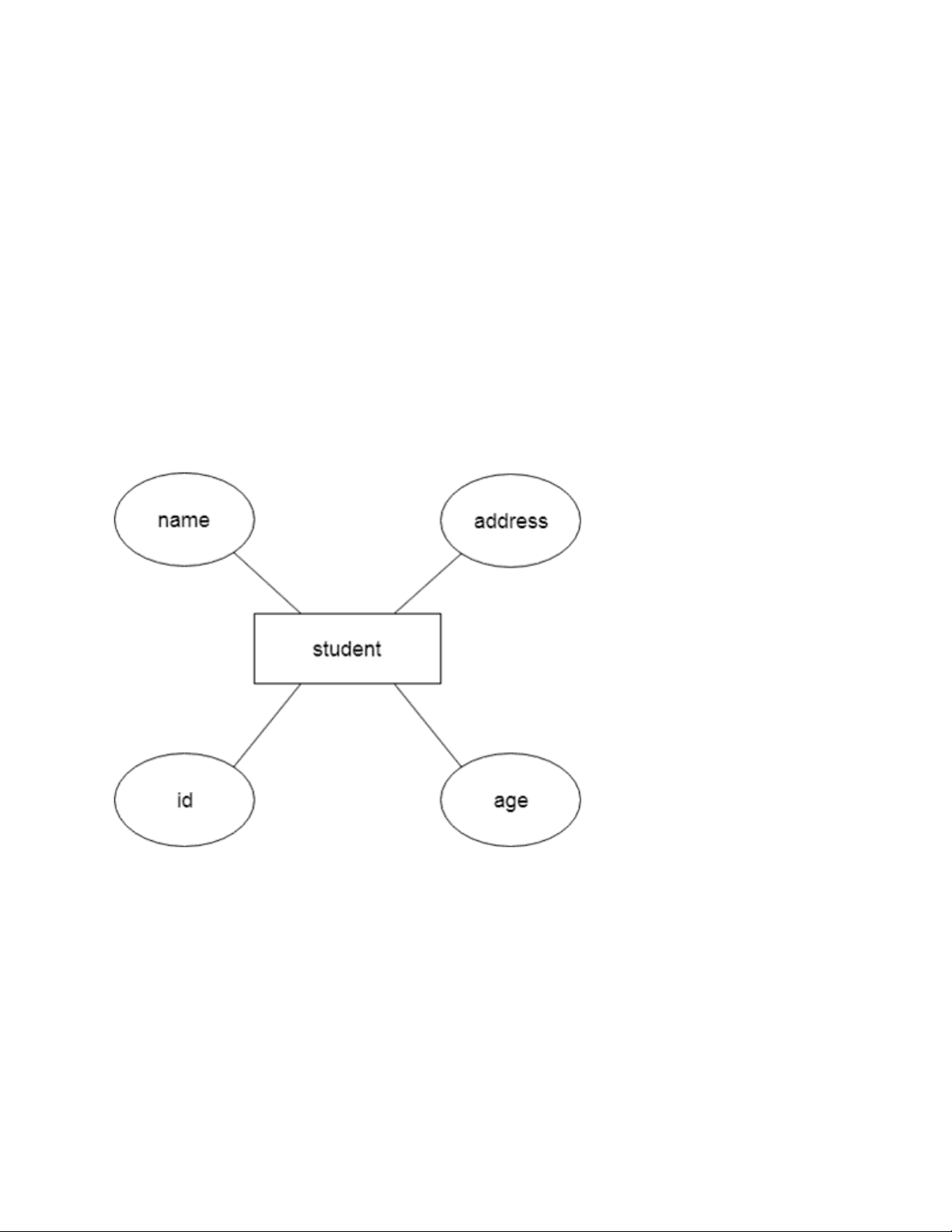
- In ER modeling, the database structure is portrayed as a diagram called an entity- relationship diagram. For example, Suppose we design a school database. In this database, the student will be an entity with attributes like address, name, id, age, etc. The address can be another entity with attributes like city, street name, pin code, etc and there will be a relationship between them.
Component of ER Diagram
1. Entity:
An entity may be any object, class, person or place. In the ER diagram, an entity can be represented as rectangles. Consider an organization as an example- manager, product, employee, department etc. can be taken as an entity. a. Weak Entity Skip Ad
b. Composite Attribute An attribute that composed of many other attributes is known as a composite attribute. The composite attribute is represented by an ellipse, and those ellipses are connected with an ellipse. c. Multivalued Attribute An attribute can have more than one value. These attributes are known as a multivalued attribute. The double oval is used to represent multivalued attribute. For example, a student can have more than one phone number.
d. Derived Attribute An attribute that can be derived from other attribute is known as a derived attribute. It can be represented by a dashed ellipse. For example, A person's age changes over time and can be derived from another attribute like Date of birth.
3. Relationship
A relationship is used to describe the relation between entities. Diamond or rhombus is used to represent the relationship.
When more than one instance of the entity on the left, and more than one instance of an entity on the right associates with the relationship then it is known as a many-to-many relationship. For example, Employee can assign by many projects and project can have many employees.
Notation of ER diagram
Database can be represented using the notations. In ER diagram, many notations are used to express the cardinality. These notations are as follows: Fig: Notations of ER diagram
ER Design Issues
users often mislead the concept of the elements and the design process of the ER diagram. Thus, it leads to a complex structure of the ER diagram and certain issues that does not meet the characteristics of the real-world enterprise model. Here, we will discuss the basic design issues of an ER database schema in the following points:
1) Use of Entity Set vs Attributes
The use of an entity set or attribute depends on the structure of the real-world enterprise that is being modelled and the semantics associated with its attributes. It leads to a mistake when the user use the primary key of an entity set as an attribute of another entity set. Instead, he should use the relationship to do so. Also, the primary key attributes are implicit in the relationship set, but we designate it in the relationship sets.
2) Use of Entity Set vs. Relationship Sets
It is difficult to examine if an object can be best expressed by an entity set or relationship set. To understand and determine the right use, the user need to designate a relationship set for describing an action that occurs in-between the entities. If there is a requirement of representing the object as a relationship set, then its better not to mix it with the entity set. 1
3) Use of Binary vs n-ary Relationship Sets
Generally, the relationships described in the databases are binary relationships. However, non- binary relationships can be represented by several binary relationships. For example, we can create and represent a ternary relationship 'parent' that may relate to a child, his father, as well as his mother. Such relationship can also be represented by two binary relationships i.e, mother and father, that may relate to their child. Thus, it is possible to represent a non-binary relationship by a set of distinct binary relationships.
4) Placing Relationship Attributes
The cardinality ratios can become an affective measure in the placement of the relationship attributes. So, it is better to associate the attributes of one-to-one or one-to-many relationship sets with any participating entity sets, instead of any relationship set. The decision of placing the specified attribute as a relationship or entity attribute should possess the charactestics of the real world enterprise that is being modelled. For example , if there is an entity which can be determined by the combination of participating entity sets, instead of determing it as a separate entity. Such type of attribute must be associated with the many-to-many relationship sets.
Many-to-one
In one-to-many mapping, an entity in E1 is associated with at most one entity in E2, and an entity in E2 is associated with any number of entities in E1.
Many-to-many
In many-to-many mapping, an entity in E1 is associated with any number of entities in E2, and an entity in E2 is associated with any number of entities in E1. Keep Watching Competitive questions on Structures in Hindi 00: / 03:
Keys
- Keys play an important role in the relational database.
- It is used to uniquely identify any record or row of data from the table. It is also used to establish and identify relationships between tables. For example, ID is used as a key in the Student table because it is unique for each student. In the PERSON table, passport_number, license_number, SSN are keys since they are unique for each person.
Types of keys:
3. Super Key
Super key is an attribute set that can uniquely identify a tuple. A super key is a superset of a candidate key. For example: In the above EMPLOYEE table, for(EMPLOEE_ID, EMPLOYEE_NAME), the name of two employees can be the same, but their EMPLYEE_ID can't be the same. Hence, this combination can also be a key. 3 The super key would be EMPLOYEE-ID (EMPLOYEE_ID, EMPLOYEE-NAME), etc.
4. Foreign key
- Foreign keys are the column of the table used to point to the primary key of another table.
- Every employee works in a specific department in a company, and employee and department are two different entities. So we can't store the department's information in the employee table. That's why we link these two tables through the primary key of one table.
- We add the primary key of the DEPARTMENT table, Department_Id, as a new attribute in the EMPLOYEE table.
- In the EMPLOYEE table, Department_Id is the foreign key, and both the tables are related.
5. Alternate key
There may be one or more attributes or a combination of attributes that uniquely identify each tuple in a relation. These attributes or combinations of the attributes are called the candidate keys. One key is chosen as the primary key from these candidate keys, and the remaining candidate key, if it exists, is termed the alternate key. In other words, the total number of the alternate keys is the total number of candidate keys minus the primary key. The alternate key may or may not exist. If there is only one candidate key in a relation, it does not have an alternate key. For example, employee relation has two attributes, Employee_Id and PAN_No, that act as candidate keys. In this relation, Employee_Id is chosen as the primary key, so the other candidate key, PAN_No, acts as the Alternate key.
7. Artificial key
The key created using arbitrarily assigned data are known as artificial keys. These keys are created when a primary key is large and complex and has no relationship with many other relations. The data values of the artificial keys are usually numbered in a serial order. For example, the primary key, which is composed of Emp_ID, Emp_role, and Proj_ID, is large in employee relations. So it would be better to add a new virtual attribute to identify each tuple in the relation uniquely.
Generalization
- Generalization is like a bottom-up approach in which two or more entities of lower level combine to form a higher level entity if they have some attributes in common.
- In generalization, an entity of a higher level can also combine with the entities of the lower level to form a further higher level entity.
- Generalization is more like subclass and superclass system, but the only difference is the approach. Generalization uses the bottom-up approach.
- In generalization, entities are combined to form a more generalized entity, i.e., subclasses are combined to make a superclass. For example, Faculty and Student entities can be generalized and create a higher level entity Person.
Specialization
- Specialization is a top-down approach, and it is opposite to Generalization. In specialization, one higher level entity can be broken down into two lower level entities.
- Specialization is used to identify the subset of an entity set that shares some distinguishing characteristics.
- Normally, the superclass is defined first, the subclass and its related attributes are defined next, and relationship set are then added. For example: In an Employee management system, EMPLOYEE entity can be specialized as TESTER or DEVELOPER based on what role they play in the company.
Aggregation
In aggregation, the relation between two entities is treated as a single entity. In aggregation, relationship with its corresponding entities is aggregated into a higher level entity. For example: Center entity offers the Course entity act as a single entity in the relationship which is in a relationship with another entity visitor. In the real world, if a visitor visits a coaching center
There are some points for converting the ER diagram to the table:
- Entity type becomes a table. In the given ER diagram, LECTURE, STUDENT, SUBJECT and COURSE forms individual tables.
- All single-valued attribute becomes a column for the table. In the STUDENT entity, STUDENT_NAME and STUDENT_ID form the column of STUDENT table. Similarly, COURSE_NAME and COURSE_ID form the column of COURSE table and so on.
- A key attribute of the entity type represented by the primary key. In the given ER diagram, COURSE_ID, STUDENT_ID, SUBJECT_ID, and LECTURE_ID are the key attribute of the entity.
- The multivalued attribute is represented by a separate table. In the student table, a hobby is a multivalued attribute. So it is not possible to represent multiple values in a single column of STUDENT table. Hence we create a table STUD_HOBBY with column name STUDENT_ID and HOBBY. Using both the column, we create a composite key.
- Composite attribute represented by components. In the given ER diagram, student address is a composite attribute. It contains CITY, PIN, DOOR#, STREET, and STATE. In the STUDENT table, these attributes can merge as an individual column.
- Derived attributes are not considered in the table.
In the STUDENT table, Age is the derived attribute. It can be calculated at any point of time by calculating the difference between current date and Date of Birth. Using these rules, you can convert the ER diagram to tables and columns and assign the mapping between the tables. Table structure for the given ER diagram is as below:
Relationship of higher degree
The degree of relationship can be defined as the number of occurrences in one entity that is associated with the number of occurrences in another entity. There is the three degree of relationship:
- One-to-one (1:1)
- One-to-many (1:M)
- Many-to-many (M:N)
1. One-to-one
- In a one-to-one relationship, one occurrence of an entity relates to only one occurrence in another entity.
- A one-to-one relationship rarely exists in practice.
- For example: if an employee is allocated a company car then that car can only be driven by that employee.
- Therefore, employee and company car have a one-to-one relationship.